Tuesday, November 12, 2013

VBC Racing WildFire D06 Building Blog Step 25-26

Step 25 Install Front and Rear Stabilizers

Just follow the manual to assemble Anti-Roll Bars and Rear buckles. Please note: For the Front Stabilizers, tighten the set screw with 3mm (not 4mm) from the edge of the stabilizer. Beware if you make it 4mm, the Stabilizer Turnbuckles may "kiss" your Front drive-shafts. Well, you can adjust it later anyway.

Step 26 Install Front and Rear Stabilizers

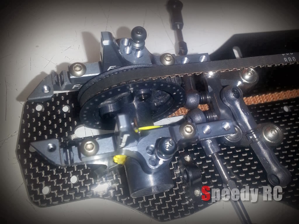
Now, After install the Stabilizer mounts, insert and adjust those set screws. Verify if the Anti-Roll Bars rotate with minimum free play.
Final Verification: Lift one of  front and rear arms, verify if the arms on another side will lift freely as well without too much delay. Normally both arms will lift up the same or nearly the same distance. If working fine then your Stabilizer System is setup ready.

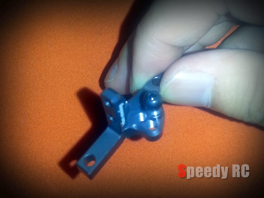
BTW, I like the Front "Bug" head design! LOL

<<-Visit SpeedyRC Online eStore

VBC Racing WildFire D06 Building Blog Step 21-24

Step 21 Front Suspension Assembly

Front Suspension Assembly Part 1
Justify the direction of Arms as above.

Installation of Anti-Roll bar Turnbuckle.

Insert Suspension Arm Pin with Shim Spacers. plug the Anti-Roll bar Turnbuckles into the inside plastic ball-end as above.

Step 21 Front Suspension Assembly 2

And then, install Front F00 Suspension Mount with Shim. Follow the instruction, do it the same way as Rear Suspension Mount assembly. You will need pre-lubrication and fin-shim as well.

Step 23 Front Suspension Assembly 3

VBC has built up the Two-Piece Joint Drive Axle for us already. Sweet! You have to lubricate them before assembly. Apply the Grease on both sides. Then follow instruction to assemble Front Steering Blocks and C-Hubs. Most of processes are pretty similar to Rear Suspension Assembly that I don't want to repeat again here.
Pretty Straight forward but just one thing you need to double-check: Make sure you install the C-Hubs in correct L and R place.

Step 24 Front Suspension Assembly 4

Measure the length of Upper Turnbuckles with Caliper. Again, be caution about the size of Turnbuckle Cups, thinner one to outside and Thicker one to inside.

 Now, the whole kit is nearly accomplished. Well done!

Monday, November 11, 2013

VBC Racing WildFire D06 Building Blog Step 18-20

Step 18 Rear Suspension Arm Assembly

Rear Suspension Arm Assembly
Open bag 18-20, place the 2 Rear Arms as shown on Picture above.

Insert M4x10 Set Screw from the top of the suspension arm for adjusting down stop. Initial setting is 1.8mm measuring from the bottom part of the arm for both sides.

Insert M3x10 Set Screw into the most outward hole at rear of Arm. Be caution, do not screw in too much. leave about 4mm long at outside.

Insert the 5mm length Ball Connector to the second outward hole in the front of Arm. Completely screw in.

Follow the user manual, insert the Suspension Arm Pin (inward) with 3mm Arm Spacer in front, 1mm at rear. I have to say it again, the quality of plastic from VBC Racing is so good that you don't have to do any reamer or sanding job.

Now, Let's find the grease box from the pack box. It is made by MR ROCHE. Nice!
But just too little. Why not give me a full box : (
Use your hex driver or something to dip a little bit at a time.

Apply it into the Center Arm Mount Block first. Then insert the Pivot Ball.

Then, apply it into Rear Suspension Mount. You can apply a bit on Arm Pin Pivot Ball as well.
Please note: The Factory Rear Suspension Mount is E30, which stands for 3 Degree if Center Arm Mount is C0. I just have the optional part E25.

Assemble the Rear Suspension System. Once again, Do not tighten up those rear screws before the Rear Suspension Shim inserted. After that, fasten Screws.

Before finish Step 18, you may notice that a little slop between Suspension Arms and mounting Blocks.
Open the 3mm shim spacer bags. Get yourself some 0.2mm or 0.3mm shim to fine-shim them.

Step 19 Rear Suspension Arm Assembly Part 2

Rear Suspension Arm Assembly Part 2
We have to say Thank You to VBC Racing cause they have done some most complicate jobs for us in advance. Those Axle Drive Shafts have been assembled already. Very nice!
What you need to do is lubrication. dip a bit into the Axle Joint, spin around, re-apply if needed.

Follow the instruction manual to assemble Rear Suspension Upright with Ball Bearing and Upper Ball Connectors.

Wait a minute, What's that? I am pretty sure it is a typo. Haha.

Step 20 Rear Suspension Arm Assembly Part 3

Rear Suspension Arm Assembly Part 3
Assemble the Turnbuckles. Use caliper to measure the length between edge of cups.

Be caution about the Turnbuckle cup size. The Thicker Cup is for connect to inside Bulkhead and the thinner Cup is for outside Upright.

Insert the M3x23 Upright Pin into Arm, Place the 0.5mm Shim at the rear.

After insert the Upright Pins and set screws, You need to insert  Shaft Pin on the other end with Shaft End Shoe.Just note The Lock
Slot Direction, then use the tiny M3x2 Set Screw to lock it up.
Rear Suspension System setup finish.
Final verification: lift both arms then release, justify if Arms can rotate freely without slop.

<<-Visit SpeedyRC Online eStore

VBC Racing WildFire D06 Building Blog Step 15-17

Step 15 Front Drive Train Assembly - Spool Assembly


Front Drive Train Assembly.
Front Spool (A) and Belt Guide (B).
Please be careful about the node spot. Apply a thin layer of CA glue on (A). Then patch (B) on it.
Be very careful about the CA glue. Do not overly apply, or it will spread out into the gear and make it impossible to clean.
Press firmly to make two parts stick together parallel.

Now then, install the Spool shaft, 10x15mm Ball Bearing, Diff Holder and Spool Drive Cup.
Spin the Drive Cup to make sure there is no tweak on spool gear.

Step 16-17 Assemble Front Upper Bulkhead


Place the spool gear into the middle of front lower bulkhead, fasten the front belt. Then cover the upper bulkhead with screws.
Tips: When you installing the upper bulkhead, place the chassis on a flat hard surface. for example, a Glass board or a RC setting board. Then press down the bulkhead with a bit pressure while tighten up screws. Doing so to eliminate possible chassis tweak.

Again, Adjust the belt tension with the yellow adjuster. In my case, I make at least 2 nodes forward.
The evolutionary design of belt tension adjuster make your tension adjustment much easier. just loose the M2x10 Round-head set screws underneath then you can move the adjuster all around. No need to take the upper bulkhead out, which save us a lots of time. Sweet!

Bulkhead setup ready! Now, install the Top Graphite deck.
Again, place the chassis on an absolutely flat surface such as glass board. Apply pressure while tighten up screws.

<<-Visit SpeedyRC Online eStore

VBC Racing WildFire D06 Building Blog Step 10-14

Step 10 Upper Deck Assembly


Let's build the Belt Tensioner. Put 3 shims in between Screw head and 2 ball bearings.

Setup done, quite easy.

Step 11 Center Pulley Assembly


Center Pulley. I have replaced the factory Spur Gear with a small size one due to I will run it in Stock class. The Factory one is for Mod class. Follow the manual to setup Pulley drive shaft and spacer.
Apply the set screw in order to lock the hinge pin.
Tips: Unless you are going to run it on indoor Carpet, it is recommended to use 48 Pitch Spur Gear for Outdoor Asphalt Race because it is more durable.
Which brand of Spur Gear with fit this car? I found out that Spur from Xray, Serpent, and Panaracer are all suitable.

Clamp in the 5mm E-Clip with Pliers to lock-up Center Pulley.

Step 12 Upper Deck Assembly 2


Before you install the Center Pulley, Please get some 5mm Shim Spacers ready. (You don't have? buy a set online or from your LHS.)
In my case, I need 2 piece of 0.1mm thickness spacers.

Place them right here. one shim on each side.

Put the two 5x8mm ball bearing into Center Pulley Bearing Holders. Place the Center Pulley in the middle with Rear Belt. Screw in to stabilize the Center Pulley.
Please note: do not over-tighten the screws on Bearing Holders. Otherwise you are taking a risky to tweak the chassis board. If you notice there are still a bit sloppy on the Pulley when it spin, insert more shims.

Step 13 Rear Upper Bulkhead Assembly


Rear Upper Bulkhead Assembly. Insert 2mm spacer in between bulkhead and ball connector.
I suggest you apply a bit of Thread-lock on Ball Connector before screw in.


Step 14 Install Rear Drive-train


Install Rear Drive-train. I suggest you loose the Belt Tension Adjuster Ring dial a bit.
Make the node point to backward for at least 2 node slots.

Place down the Diff gear with Belt Tension Adjuster. Cover up the upper Bulkheads with 4 3x8mm screws.
Rear Drive-train setup ready. Test the Belt tension with finger push.
Tips: Depends on different race class, the rule is: Make the belt tension as loose as possible but not stripping. Mod class require tighter setup on belt tension, in contrast, For Stock class, We can loose it a bit more.

Interested in this Kit? Want to know where to buy in Australia?
Come to our online store: www.speedyrc.com.au

<<-Visit SpeedyRC Online eStore

VBC Racing WildFire D06 Building Blog Step 7-9

Step 7 Steering System Assembly

Let's head to Steering System build.
Let's tear it apart!

You will find out that Front Belt is in the bag as well. leave it alone for now, Let's build the steering arms first.

You may also need some 3mm shims as well, pick them up from the box. you will get 3 bags of them with different thickness. I recommend use 0.3mm ones.

Attach one piece of shim on screw.

This is Steering Assembly Travel Plate. It is very nice to see VBC has done all bearing setup jobs for you in advance. You merely don't need to worry about the messy stuff.
What you have to be careful about is: Do not lost those Steering Cone Washers.
Tips: Place a big towel or RC setting work mat on your table. If any tiny bits and pieces dropped, they won't bounce to no-where so-that you can still get them back easily.

Setting up the Ball Connectors (7.5mm Lenght). After insert 2mm+1mm spacer, you have to apply a bit Thread-lock on it as shown above.

Step8 Steering System Assembly 2


Now, let's do Turnbuckles. For the two long ones, the connector cups edge to edge shall be 28.30mm.
Please use a caliper to measure the exact measurement. With this length, you can get a 1 degree front tow-out.

4.5mm for the shot Turnbuckle.

Step 9 Steering System Assembly 3


Alright, done. Please note, just a little bit of slop in between Steering Travel Arm and Set Screws is forgiven.
Wow, Almost forget, you have to place the Front Belt in the middle of Steering System before fully assembled.

<<-Visit SpeedyRC Online eStore