Step 18 Rear Suspension Arm Assembly
Rear Suspension Arm AssemblyOpen bag 18-20, place the 2 Rear Arms as shown on Picture above.
Insert M4x10 Set Screw from the top of the suspension arm for adjusting down stop. Initial setting is 1.8mm measuring from the bottom part of the arm for both sides.
Insert M3x10 Set Screw into the most outward hole at rear of Arm. Be caution, do not screw in too much. leave about 4mm long at outside.
Insert the 5mm length Ball Connector to the second outward hole in the front of Arm. Completely screw in.
Follow the user manual, insert the Suspension Arm Pin (inward) with 3mm Arm Spacer in front, 1mm at rear. I have to say it again, the quality of plastic from VBC Racing is so good that you don't have to do any reamer or sanding job.
Now, Let's find the grease box from the pack box. It is made by MR ROCHE. Nice!
But just too little. Why not give me a full box : (
Use your hex driver or something to dip a little bit at a time.
Apply it into the Center Arm Mount Block first. Then insert the Pivot Ball.
Then, apply it into Rear Suspension Mount. You can apply a bit on Arm Pin Pivot Ball as well.
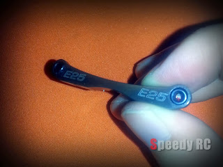
Please note: The Factory Rear Suspension Mount is E30, which stands for 3 Degree if Center Arm Mount is C0. I just have the optional part E25.
Assemble the Rear Suspension System. Once again, Do not tighten up those rear screws before the Rear Suspension Shim inserted. After that, fasten Screws.
Before finish Step 18, you may notice that a little slop between Suspension Arms and mounting Blocks.
Open the 3mm shim spacer bags. Get yourself some 0.2mm or 0.3mm shim to fine-shim them.
Step 19 Rear Suspension Arm Assembly Part 2
Rear Suspension Arm Assembly Part 2We have to say Thank You to VBC Racing cause they have done some most complicate jobs for us in advance. Those Axle Drive Shafts have been assembled already. Very nice!
What you need to do is lubrication. dip a bit into the Axle Joint, spin around, re-apply if needed.
Follow the instruction manual to assemble Rear Suspension Upright with Ball Bearing and Upper Ball Connectors.
Wait a minute, What's that? I am pretty sure it is a typo. Haha.
Step 20 Rear Suspension Arm Assembly Part 3
Rear Suspension Arm Assembly Part 3Assemble the Turnbuckles. Use caliper to measure the length between edge of cups.
Be caution about the Turnbuckle cup size. The Thicker Cup is for connect to inside Bulkhead and the thinner Cup is for outside Upright.
Insert the M3x23 Upright Pin into Arm, Place the 0.5mm Shim at the rear.
After insert the Upright Pins and set screws, You need to insert Shaft Pin on the other end with Shaft End Shoe.Just note The Lock
Slot Direction, then use the tiny M3x2 Set Screw to lock it up.
Rear Suspension System setup finish.
Final verification: lift both arms then release, justify if Arms can rotate freely without slop.
<<-Visit SpeedyRC Online eStore


No comments:
Post a Comment