Wednesday, December 18, 2013

Review and Tips for VBC Wildfire D06

After running this kit for a month, I would like to give it a review and express some thoughts and tips.
First of all, I would like to give it a thumb up for the quality parts.

The carbon fibre chassis is very smooth and flat. It gives me the same smooth feeling as X-Ray T4-14. I am quite sure it uses the same standard of quality of Graphit. Compare to its predecessor Wildfire Dynamic, it is a great improvement.

The plastic parts are still strong but not as harsh as its old version. The colour is dyed to black as well, which is what I expect for. Aluminium parts are as always, tough and fine.

Things I really like: very smooth Gear Diff. if you have set it right, it will give you butter-like feeling that I never got from my old TCs. Also, all Alum ball-ends and turn buckles are join up quite smooth with no sloppy. I don’t have to squeeze the plastic turn buckles to free out the joins. Thumb-up!

Building process is flawless as well. All parts bags are clearly tagged with step labels. VBC provides you spare small parts like shims, clips as well. Sweet!

Over all, the quality of the build is quite out of expectation because I spend  a little bit more than $400 for the top-end quality car kit (normally cost more than $500).

Now, to the driving experience, I have setup the car with electronics and parts as below:

  • ESC: Hobbywing Xerun V3.1
  • Motor: Team Trinity Kill shot 13.5T with RPM Stator and 12.5mm High Torque Rotor
  • Servo: XPERT Low-Profile Brushless Servo 6.6v 12kg 0.076sec #PI-3401 LV 
  • TX/RX: Sanwa M12/RX-471
  • Battery: Team Zombie LiPo Rampage Series 7.4v 7200MAH (ROAR Approved)
  • Body: Blitz WRZ 190mm (light weight 0.7mm)
  • Wheels: Team Sorex 36R with soft inserts


I run it in my local club B.R.C.C.C Bay side Wynnum outdoor asphalt track. The track is combination of multiple shot hairpin turns and medium sweep turn with about 50m straights, Medium to bumpy track Surface.

At first, I run it with factory base setup. I instantly feel the car with a lot of steering enter into the corner. In the middle of cornering, rear wheels can still remain calm and stable till out of corner. I am impressed about the initial performance of this car.

After some runs, I decide to remove the front suspension shims and replace the rear ones with 0.5mm in order to eliminate the little entry corner push and give it more grips for bumpy track. I also increase front droop a little bit as well. It runs much better since those small changes.

After a few more tests, I work out the final build for the track as below:

I have to say the car got a lot of potentials and I can push it to the limit very easily because it is very responsive to any changes I made. I have asked one of fastest guys in our club to have a test and he was impressed with the corner speed of the car as well. Sweet!

Alright, let me say something I don’t like.

First of all, the Front bumper is soft. If serious crash happens, it may not be able to save your front suspension arms. I have to replace it with my Wildfire dynamics hard bumper. I think hard bumper for Xray T4 can be interchangeable.

Second, alternative Alum suspension mounts and shims are not included in the package. If you want to fine tune the car, you have to go buy them separately, although the car is very fast from initial. Those Alum parts are not cheap.

Now, here are some tips:
  • Remember to re-lube Arm Pin Pivot Balls (B-02-VBC-0035) after a few runs to protect the suspension system.
  • Keep some C-hubs, spool out-drives and steering blocks as spare although they are quite strong but you never know what will happen on track and when you will need them.
  • Cleaning and lubrication is your must-do task after each race. Bearing, shims, drive shaft joints are the parts you should always look after.
  • If you feel gear biting from turning your gear diff, it is time for rebuild. Also, if you feel some bubble sound inside the damper when you squeeze it, you need to rebuild it as well.
  • Green slime from AE is the best product for sealing your gear diff and shock dampers after rebuild.
  • Drive safe. ^_^


Tuesday, December 10, 2013

Tuesday, December 3, 2013

Friday, November 29, 2013

My first ever airbrush painting attempt

Got my airbrush kit for a while but haven't got a chance to try it with my new purchased car body.
Finally I got it done last night.
A bit messy and imperfect. Anyway, I just want to memorize this first ever attempt :)


Sunday, November 24, 2013

Where can you get a good setting board but real cheap?

Are you still looking for a good setting board but don't want to pay for those big brands with big price tag?
Here is a good one bounce to you:
Guess where have I found this?
Yeah you are right. IKEA!!!
Perfect flat glass top 48x40cm, with only $15. You get yourself a perfect setting board for either 1/10 or 1/8 RC car/truck!!!
Still have no idea what is it?
Come on man.
I pass you a link now:
http://www.ikea.com/au/en/catalog/products/40202384/


<<-Visit SpeedyRC Online eStore

Sunday, November 17, 2013

How to Shorten lead for RC Servo and Fan

Today I gotta share with you my experience of How to Shorten lead for RC Servo and Fan.

Preparation:


  • JR/Futaba plugs for replacement.
  • Scissors.
  • Hobby/Carve Knife.
  • Crimping Tool or Pliers.
  • Solder Station.


Now I am going to shorten the lead of my Motor Fan. I have all stuff ready. Now let's begin.

Measurement and Cutting 

Place your fan on a flat surface. Identify the correct polarity and remember.

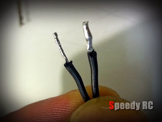
Measure the desire length, cut it with scissors, then split it to 2 leads in Y shape. (For servo lead, you have to split it into 3). Make each of single lead 25mm long.


Use Hobby knife to slightly round-cut the rubber insulators for 10cm from the top, then tear them out.
Use your finger to twist the lead for better shape.

Soldering 

Now, get your Solder Station pre-heat ready to about 250 Degree C.

Use Solder Iron Tip with a bit melt solder to gild the leads. Make a thin cover around them.

Then, after cool down, you have to cut them into the same length at  around 5mm.

Installation

Now, make a plug and tips ready. For fan, you need 2 tips. For servo, you need 3.

Measure the length as above. Re-cut if needed. Be careful do not make the lead too long and place it too deep. Just make it right as above picture shown.

Use your crimping tool to squeeze the tip-tails with soldered leads. If you do not have one, you can use pliers as well but you have to squeeze around the tip-tail. Make sure they are firm and tight.
Then, heat up your solder iron again, re-gild the tips. Make them soldered together for loosen free guarantee.


Now, insert leads to the new plug. Make sure you place them with the correct polarity.
 All done. Thanks for watching!

<<-Visit SpeedyRC Online eStore

Wednesday, November 13, 2013

Team Trinity Kill Shot 13.5T Motor Open-Box Review and Motor Shimming Tips

Open-Box Review

Finally, I got my new Team Trinity Kill Shot RPM 13.5T Motor yesterday.
Here is the box, it has been opened by Customs for inspection before delivery. Hope they haven't take apart the motor . LOL.

Now, here we go! As always, instruction docos, user manuals......

Sensor wire is a bonus but way to long for on road car. Just keep it as spare.

Some closer looks. As we can see, the front panel has been re-designed with less holes but in more precise location. The 13.5 number has been printed on stator indicated the class.

Look at the back, I am surprised that Factory pre-set timing bell to 50~52 degree. Pretty high!

Motor Shimming Tips

Overall, The rotor spin very smoothly, but I feel that the rotor has no tiny bit slop movement, which means it has been shimmed very firmly. I have to re-shimmed it for better performance.
Now, Let's take out those long set-screws. Take out the back cover. Guess how many shims on the back-side of rotor?

Take a closer look, then...

Olympic!!! LOL!

Pull out the front panel as well. Carefully collect all shims. This is what the whole thing looks like.
Be caution with handling those shims, if you accidentally drop them on floor, they may bounce to no where that you can never get them back.

Let's start to put some shims onto the back of Rotor. I suggest put 3 thick one (0.3mm) first.

Then, cover up the back panel. Check the space between Sensor Unit and Rotor. Make it as close as possible but not touching. It is suggested to leave 0.8-1mm free room.

If things going OK then we insert the rotor back to stator, put the number of shims base on your test result, then cove-up back panel again.
Please note: motor shimming may vary because of manufacture deviation. In my case, I have put three 0.3mm and one 0.1mm shims on the back.

Insert the front shim spacer.

Cover-up the front panel then line up set screw holes. Insert set screws and tighten them up. Done!

Spin your rotor to verify if it can rotate freely. You have to pull the rotor forward and push backward to justify if there is a little slop. Leave it about 1mm of free play. If there is too much slop, you have to open motor again to add shims in front.

Why we have to do this? Because your motor can gain a little bit more torque with correct spacing between rotor and sensor unit. leave a little free play can also help motor produce less heat.


<<-Visit SpeedyRC Online eStore

Tuesday, November 12, 2013

VBC Racing WildFire D06 Building Blog Step 33-The End

Step 33 Electrical Components 

Due to the location of motor mount has been re-designed and moved forward a bit compare to old version, Space for ESC and Receiver is limited. You may have to spend a bit more time to work out the perfect location plan. You may have to do some cable shorten and re-route jobs as well.
Build a clean and neat car kit is always a challenging mission. LOL.

After install the front bumper and rear body post. Don't forget to setup those battery stoppers. You can also adjust the battery placement a little outward by adding shims to achieve perfect weight balance left and right.

The End

You can also buy the optional part: Motor Fan Mount (D-05-VBC-0069) with 30mm motor fan for better motor cooling.

All done for now. Just put your favorite car body on and go racing!
Thanks For watching.

<<-Visit SpeedyRC Online eStore

VBC Racing WildFire D06 Building Blog Step 29-32

Step 29-30  Install Front & Rear Shocks.


These processes are very straight forward, just follow the instruction manual then you should not encounter any issue at all.
Just bear in mind that in order to eliminate tweak, Shock Tower setup need to be done on flat surface with pressure on left and right edges of chassis while you tightening up screws to Upper Bulkhead.
PASS...

Ahh, I am highly recommend you go buy the optional part: Motor Guard. It can help protect your motor from scratch, hit or crash. Nowadays Modern TC chassis are very narrow that you will be more than likely to get your expensive motor damaged. So, to me, this part is a must-have.

Step 31 Install Motor.

Not so much things need to be mention about but one: When you adjust the motor location, please do not set the pinion too close to the spur gear. You have to leave a small gap in between, otherwise, you may strip the plastic spur gear and burn your motor because it make the motor very difficult to spin.

Step 32 Install Steering Servo

Installation of Servo is pretty straight forward as well. You may need to replace the Direct Servo Arm with Servo Saver Arm to protect your expensive servo gear. Xray and Tamiya both make very good quality Servo Savers.

 I suggest you attach a servo tape underneath of servo before assemble.

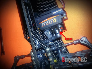
To make the Servo Arm and Turnbuckle as in-line as possible, I suggest you pick a long Button-Heard screw with 4mm spacer to link them up.
Tips: After installation, you can try to tweak the chassis with a little pressure to justify if chassis is free for flex. Then place it on your setting board to see if it remains flat.

<<-Visit SpeedyRC Online eStore